TL;DR
I replaced the faded selenium cell with a monocrystalline silicon solar panel and installed a small trimmer potentiometer in an empty cavity under the camera. A switch and a second potentiometer allows switching between the original meter sensitivity and a +1 ev calibrated sensitivity to shoot faster film than the original camera was designed for.
Backstory
When I got this camera, the meter was totally inoperable for what turned out to be two reasons:
- a small piece of tape which had apparently covered the pivot and zero adjustment screw of the meter movement had come off and migrated up towards the needle and was pinning the needle in place
- The selenium cell wasn’t putting out enough voltage, I measured its output at ~.5v in an EV16 situation (according to my other light meter). This was only enough to drive the needle about halfway across the dial to f/8 or so
I’ve read in several places that a lot of supposedly dead selenium cells are really just suffering from corroded contacts, and that cleaning the metal bits that contact the selenium panel (which is a piece of metal with a special selenium coating) can often bring old meters back to life. This might have worked for me, but I decided to install a silicon solar cell because wanted to increase the sensitivity of the meter so I could shoot Kodak 250d color cine film (which I have a roll of and is pretty easy to get). The fastest shutter speed is 1/200 so at the smallest aperture (f/16) it should still be able to expose the 250d appropriately in most situations (if I’m shooting something VERY reflective/white in full sun I might be overexposing 1 stop but we can fix that in post and honestly who cares).
I found very little info about replacing selenium cells with silicon, but did find one writeup about replacing a selenium meter cell with a silicon cell in a soviet Zenit SLR here (original site is dead, link to archive.org) (also wow tons of cool repair/disassembly/calibration writeups on that guys old zenit here)
Pics & Process
 The top cover comes off with a couple obvious screws around the edge of the camera. The long brass slider unlocks the apterture trapped needle mechanism.
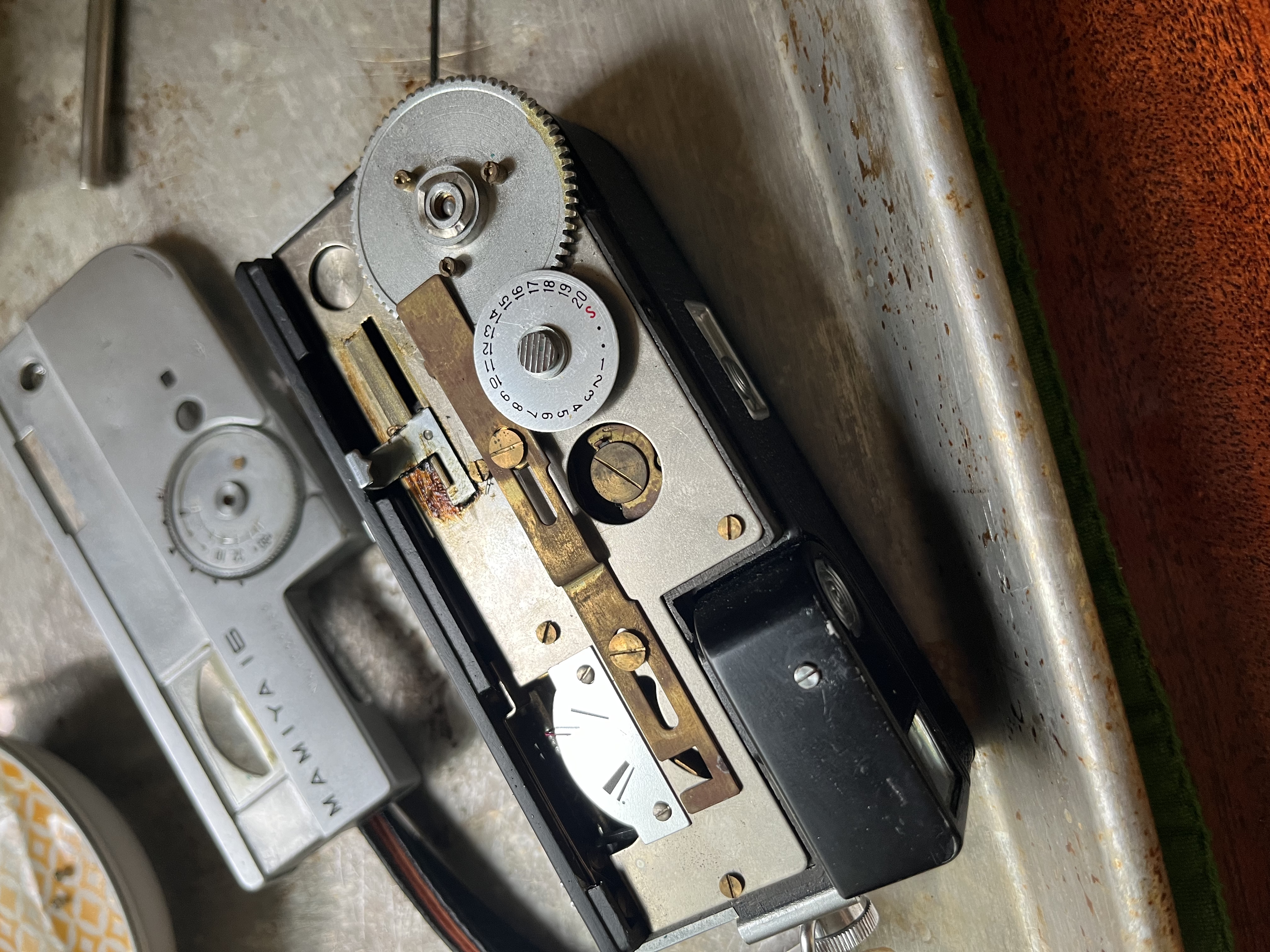
 The inner top plate is easily removed with a couple screws. Removing this plate didn’t turn out to be strictly necessary but it was interesting to see what was going on. Top right: a silver cam-type thingey that adjusts shutter speed and engages the slow-speed mechanism and B mechanism. Bottom: little armatures which control the aperture. Bottom Left: the red tip of the meter needle is visible. Left center: a little brass gear is visible coming up out of the slow-speed escapement. Upper Left: The lens varrel is visible above the slow-speed escapement. Top left: the round silver button is the underside of the shutter button.
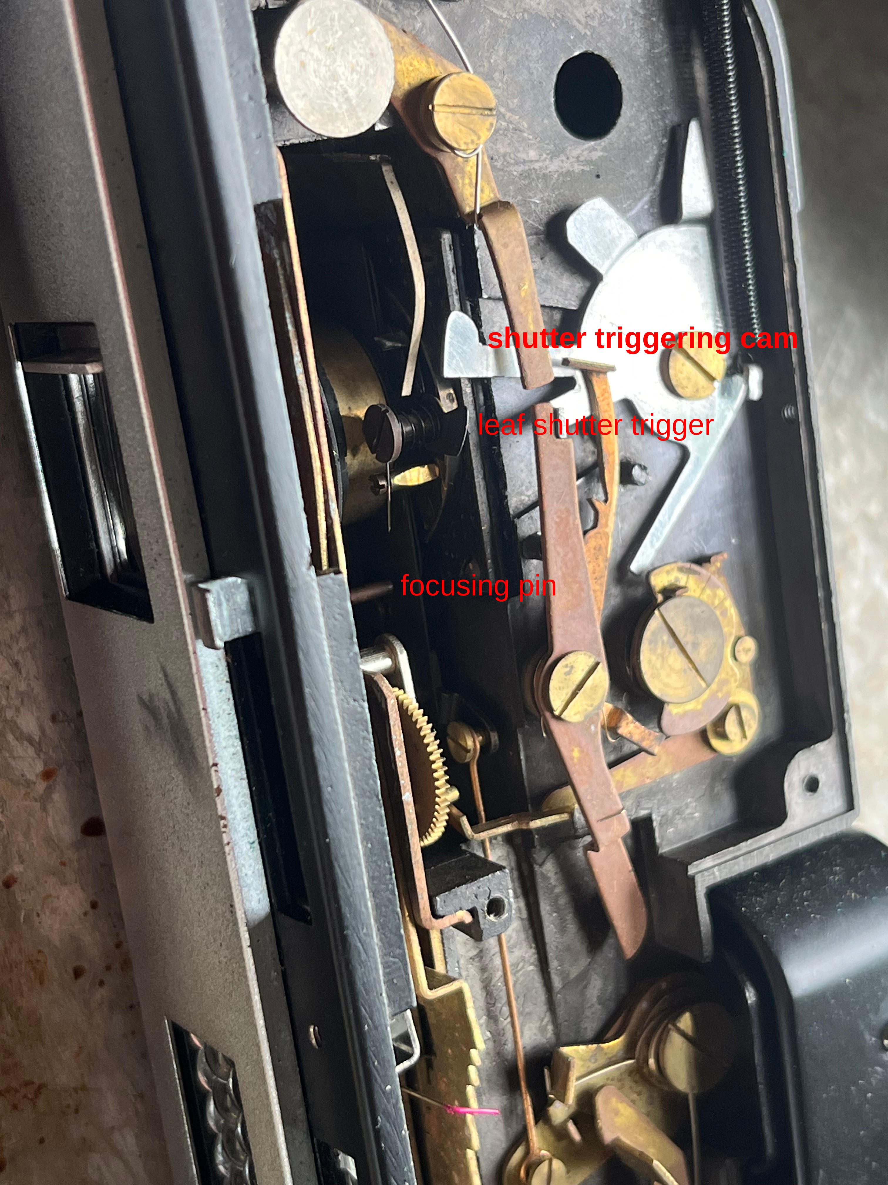 (I invented the names of these parts). The important bits of the lens are visible here: the focusing pin is spring loaded and rotates the helicoid that focuses the lens. This pin engages the sliding focus mechanism on the inner top plate. When re-installing the inner top plate, I had to pull the focusing pin upwards with a thread so that it would engage the slider correctly. The leaf shutter trigger is a small tab which apparently extends up from the top of the shutter leaf, it is triggerd by the shutter triggering cam which moves quickly (from top to bottom in this photo) when the shutter is released. The trigger is twisted a bit so that when the cam returns to the cocked position (as pictured) the trigger is pushed out of the way and the shutter does not open a second time.
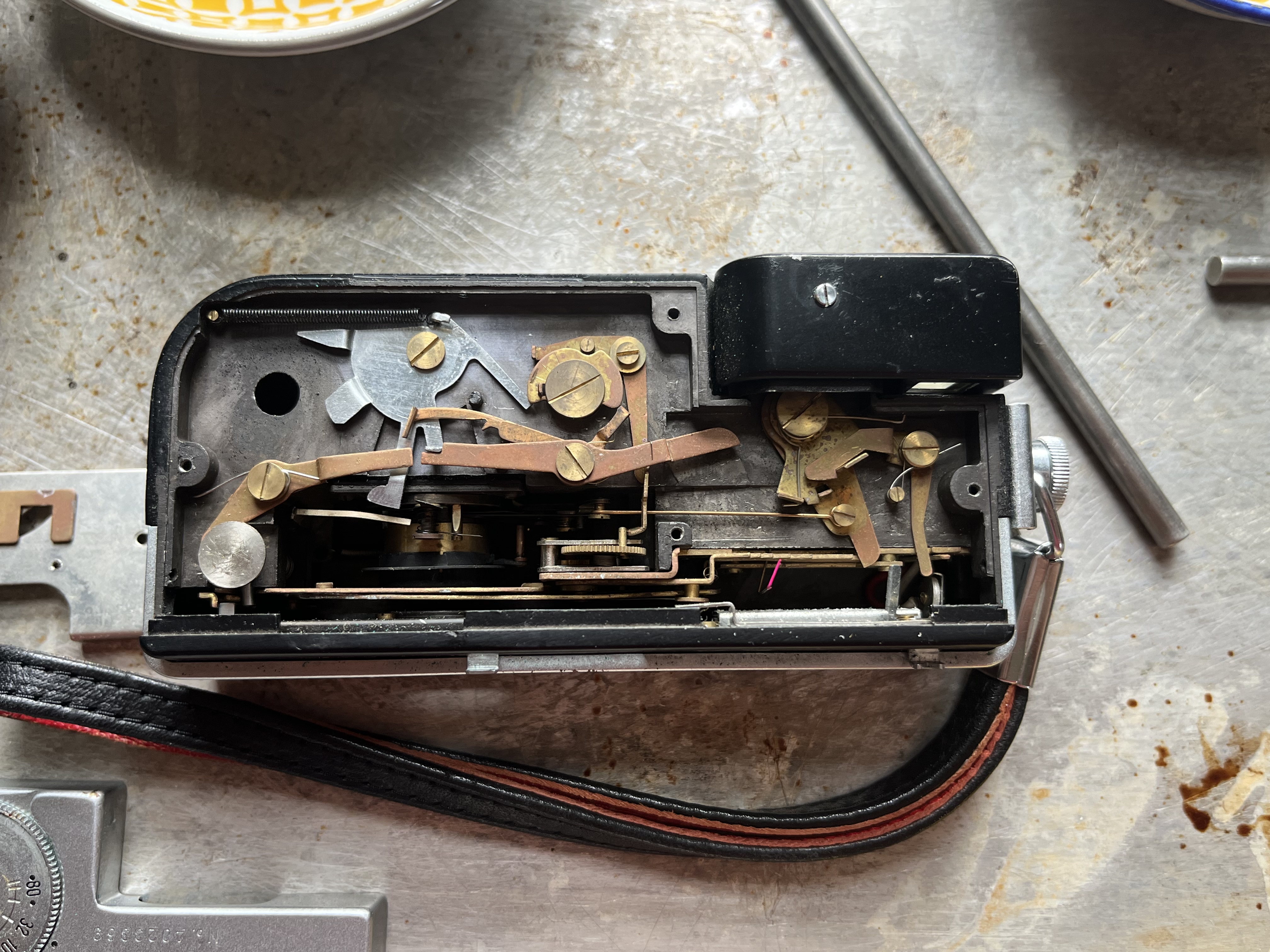
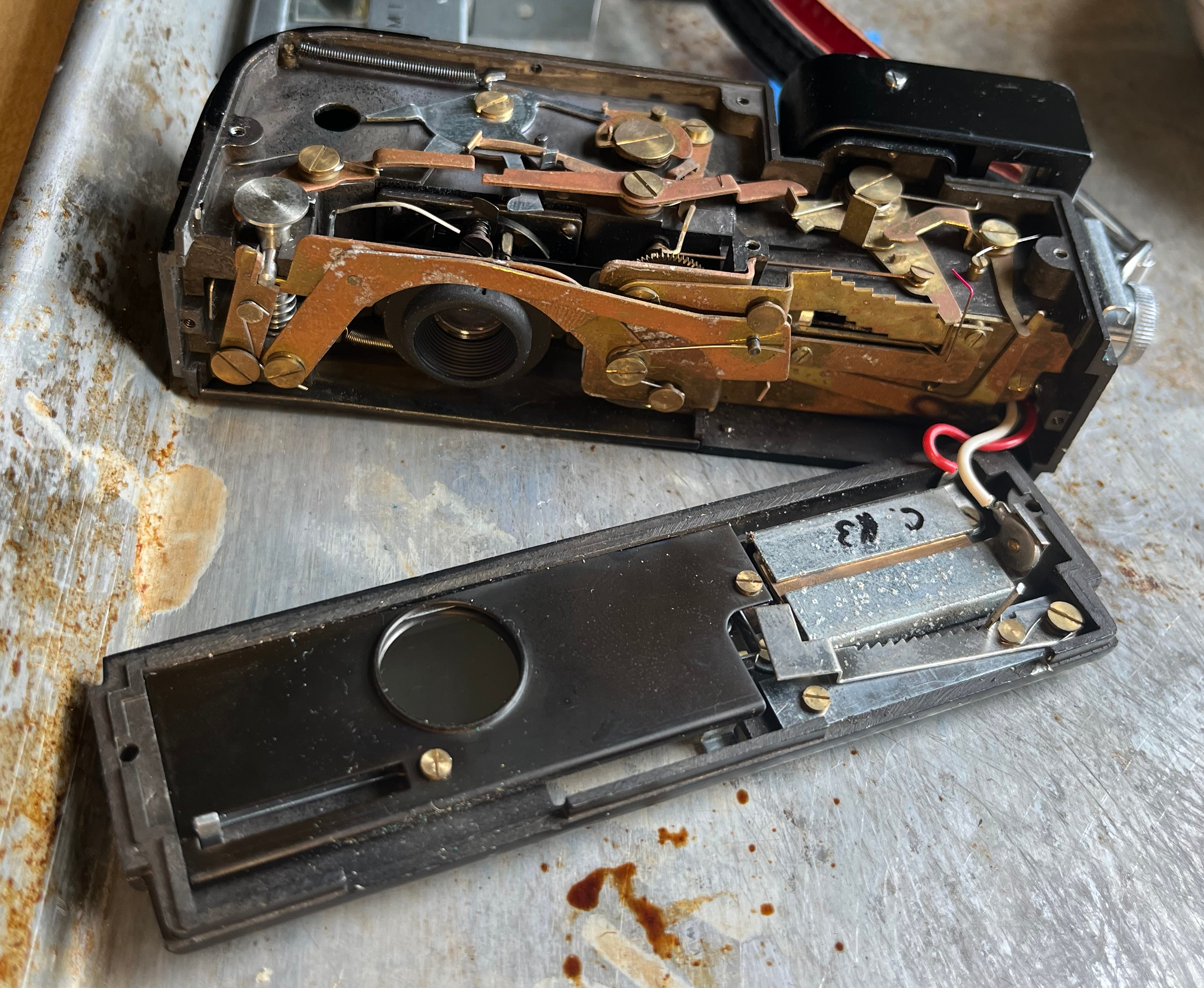 The inner front cover removed. Lots of interesting aperture related stuff going on here. The long brass arms that go over the lens trigger the meter-needle-capturing mechanism which set the aperture and in turn release the shutter. The brass piece on the front upper right of the camera is the actual device that pins the meter needle in place and sets the size of the aperture. Notice that there are 6 steps cut into it, one each for f/16, f/11 f/8 f/5.6 f/4 and f/2.8. On the inside of the front cover you can see the bracket which holds the selenium cell in place (the silver thing with the red and white wires soldered to it) and beneath that in the photo a silver arm with what looks like saw teeth cut into it. This prevents you from moving the manual aperture control slider after the needle has been trapped (which would bend the meter needle in a bad way). Advancing the film cocks the shutter, un-traps the needle, and lifts up this little sawtooth thing.
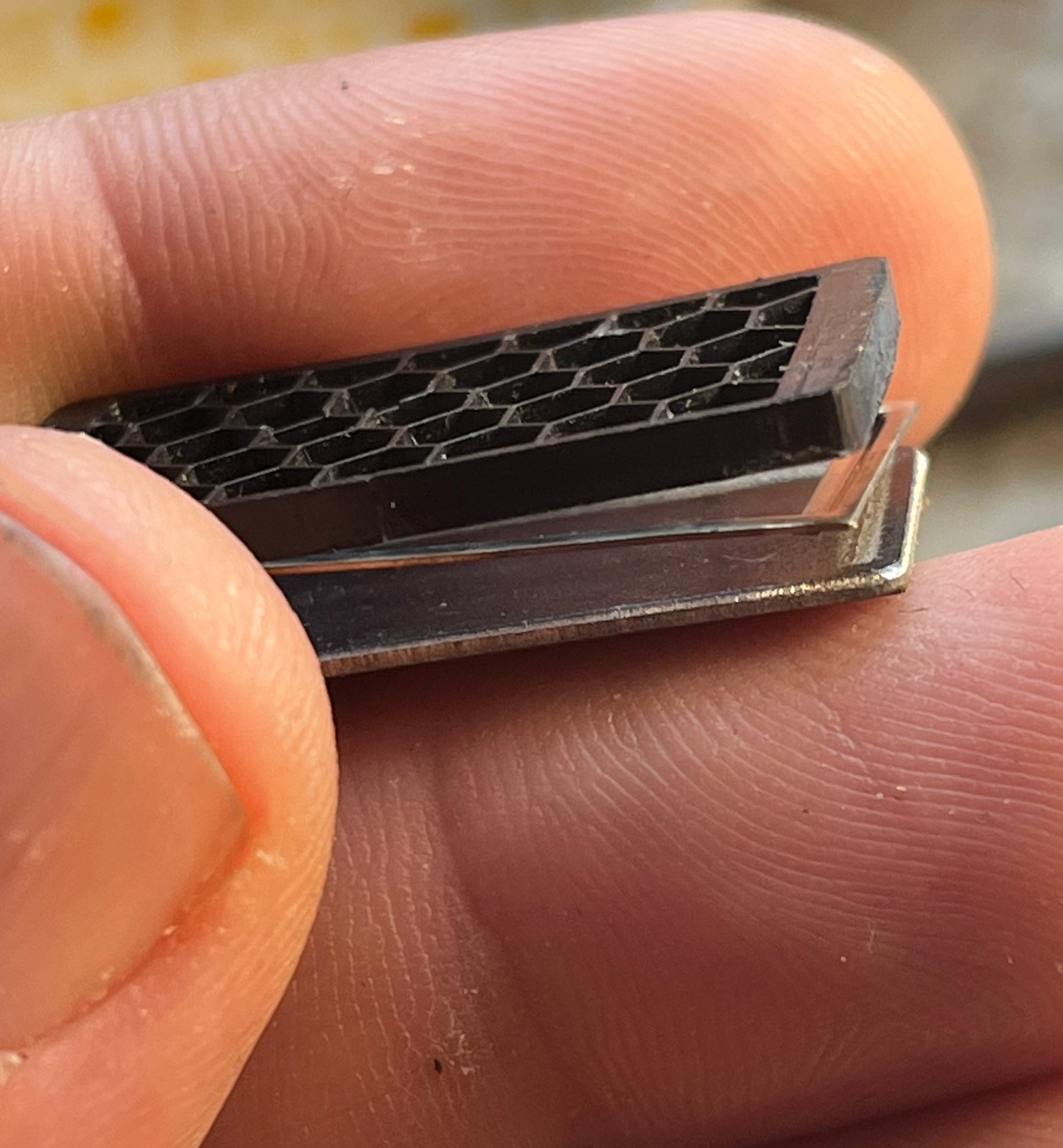 From top to bottom: Black plastic honeycomb which I assume is intended to limit the field of view of the selenium cell so that it mostly meters things in front of the camera and blocks out some light coming in from the side (and presumably especially coming in from the sky when the camera is aimed horizontally). Rectangular electrode (+) which contacs the front of the selenium cell. The actual selenium cell (the thicker-looking piece of metal with slightly rounded corners) - the front of this is a dark gray color from the selenium coating, while the back is more silver colored. At the bottom of the sandwich, just peeking out from the selenium panel, is a thin copper electrode (-).
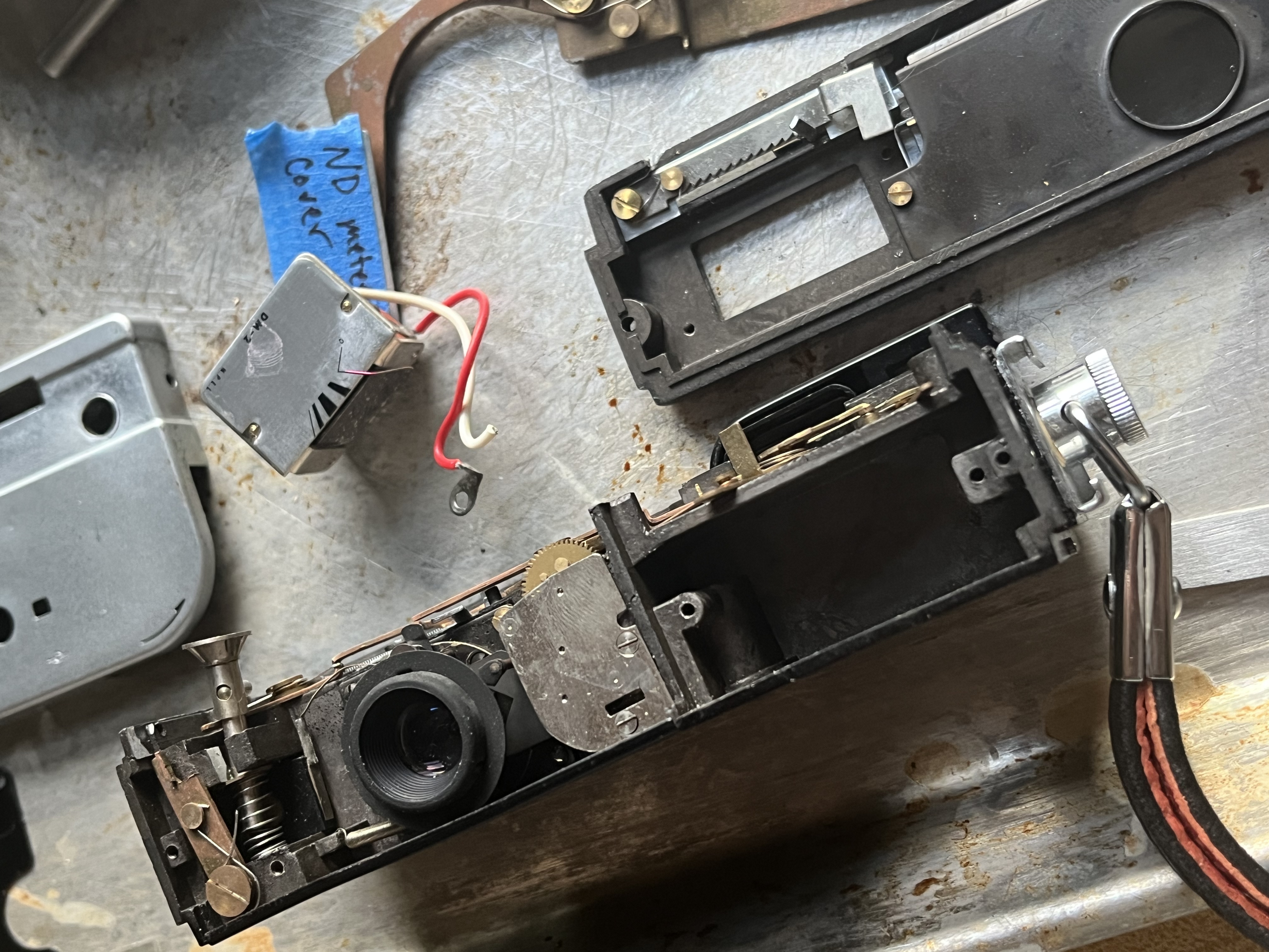 In this photo the aperture control armatures have been removed from the front of the camera to permit the actual meter itself to be removed. Mostly I pulled the meter because I was curious, but I also need to drill a small hole in the rear of the meter cavity so that I can install the calibration potentiometer. Note also that the selenium cell assembly has been removed from the inner front panel in this photo
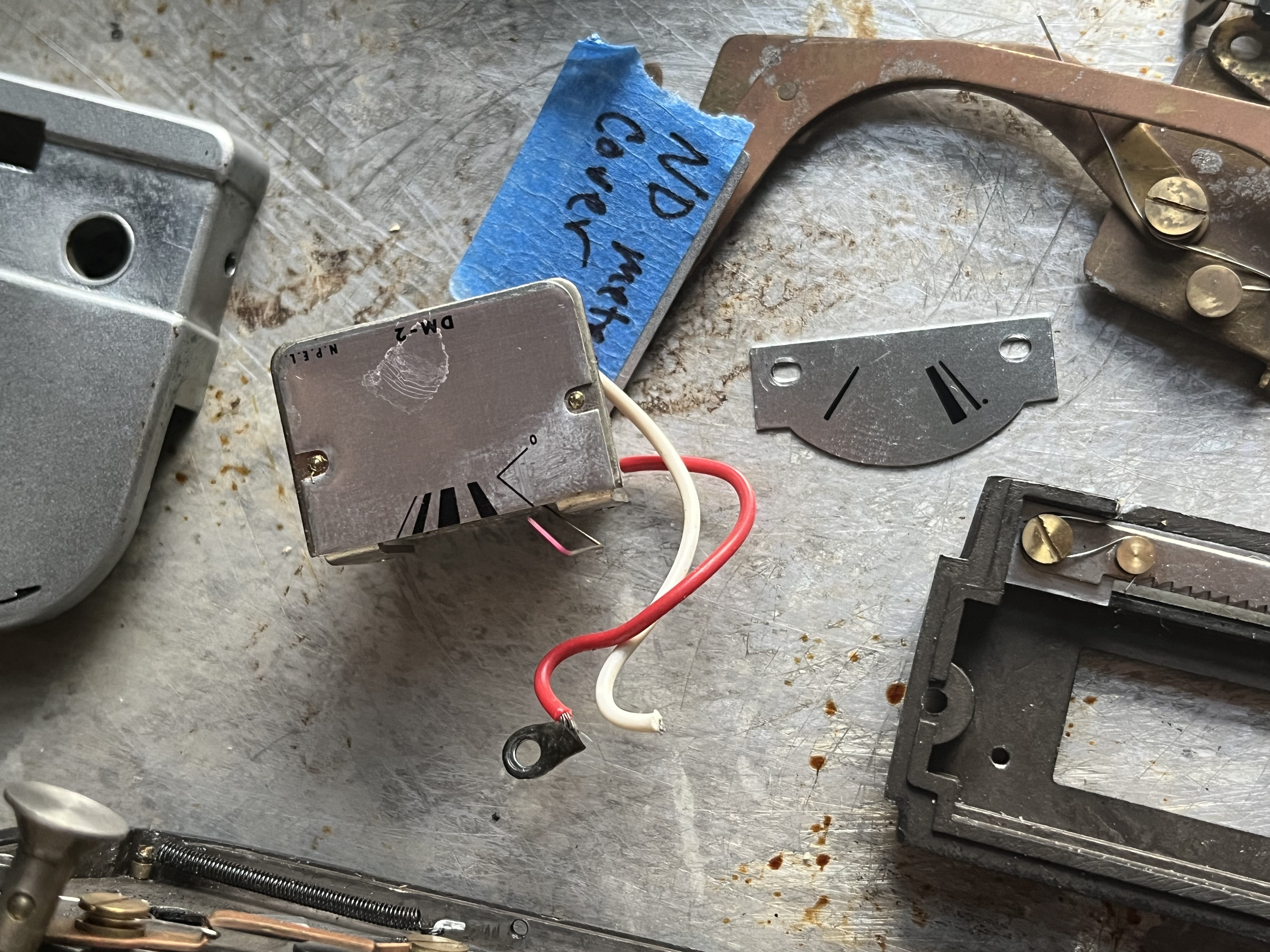 Secret meter dial!! The lower dial is the dial that’s actually visible on the top of the camera, but when I removed the meter, it turns out there’s another dial attached to the meter. Presumably this meter movement was some kind of off-the-shelf part?
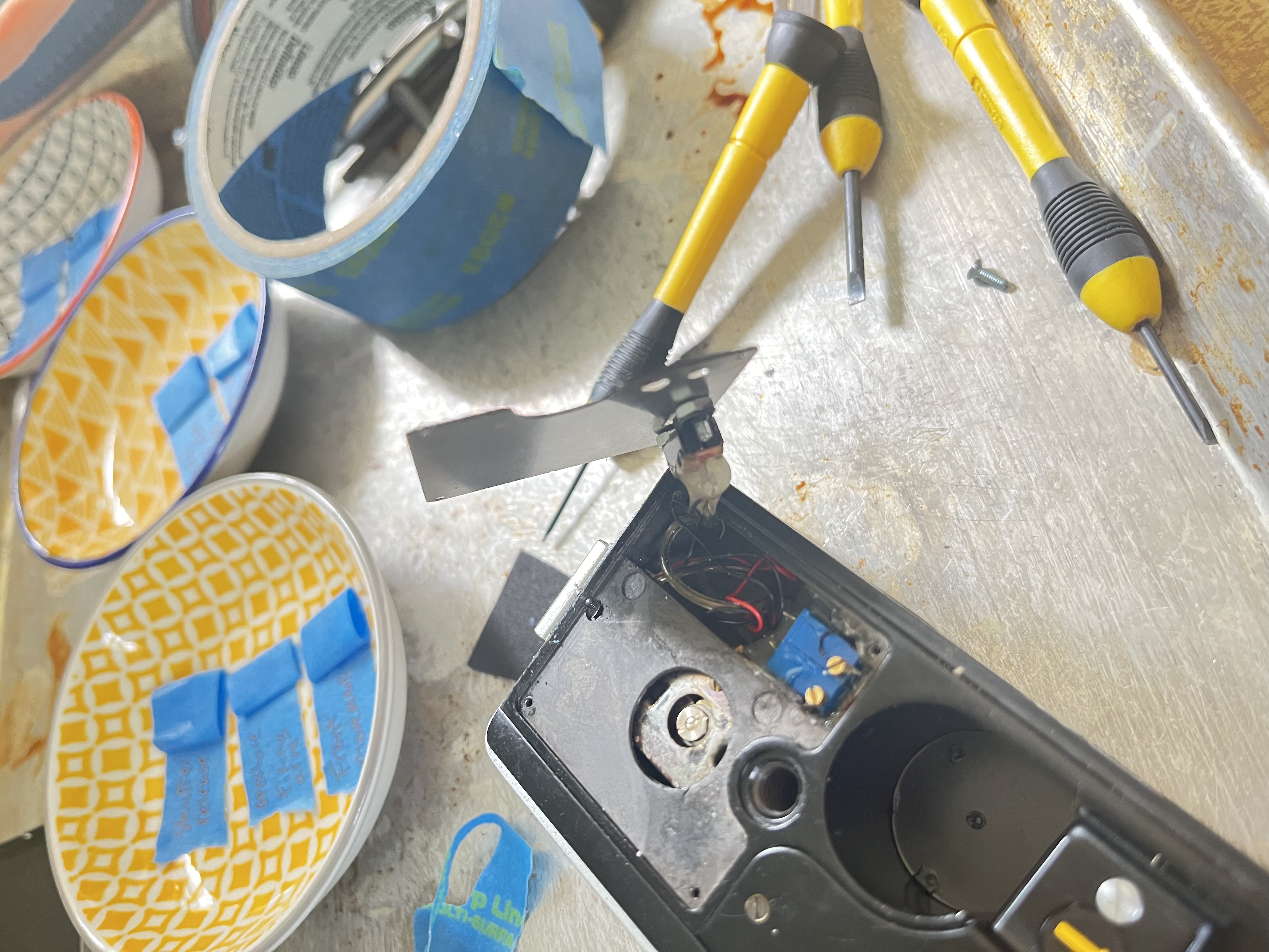
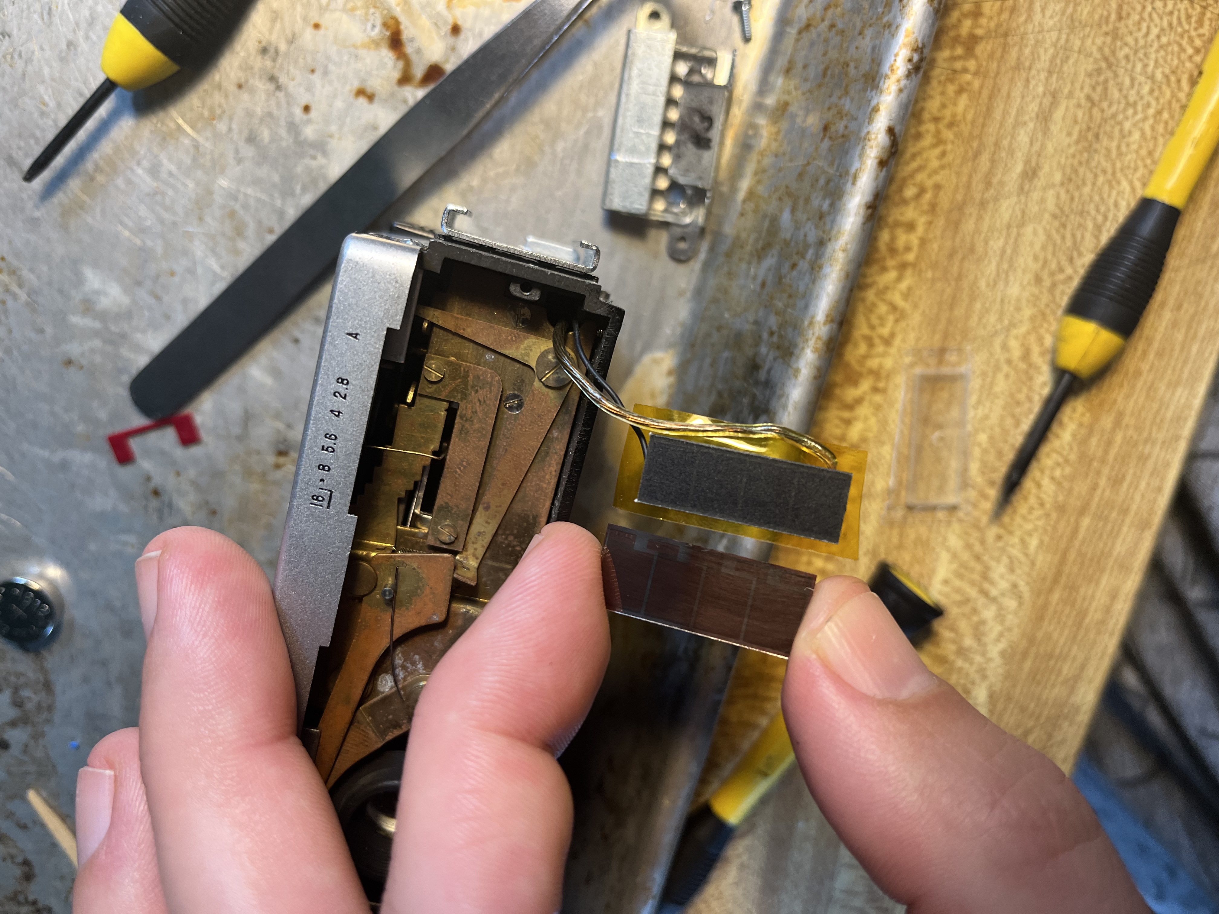 New solar cell installed. I initially installed an amorphous silicon solar panel from an old calculator (left, in my fingers), but it didn’t generate enough voltage, so I ordered a 5v monocrystalline solar cell (it’s about 23mm x 8mm) which juuuust barely put out enough juice to get the meter moving with enough sensitivity to meter correctly for 200 ISO film.
The solar cell is just connected in series with a small 250k trimmer potentiometer to permit adjustment of the meter. I ended up setting the potentiometer close to 0Ω so a smaller potentiometer could have been used.
                     calibration
                     potentiometer
┌---|solar panel|----v^v^v^---
|                       └---------|meter|---┐
└-------------------------------------------┘
 VERY conveniently, this camera has a small unused empty cavity beneath the fold-away viewfinder that I used to install a pair of trimmer potentiometers and a switch. One of the potentiometers is set slightly higher than the other and the switch selects which potentiometer is connected to the meter. This allows toggling between the original metering range marked on the camera (which tops out at ASA 100) and my increased-sensitivity range (which basically adds 1EV to the meter’s sensitivity). The potentiometers are just held in place with hot glue. A small hole (VERY CAREFULLY) drilled in the back of the meter cavity allows all this stuff to be connected without any bulging wires.
Also notice in this picture the hole in the die-cast camera body that permits access to the bottom of the meter movement. The large screw looking thing in the middle is actually a locknut for the the meter balance and should not be touched or adjuted, but the small brass screw peeking out at the edge of the hole in the body is the zero adjustment screw of the meter movement and can be used to set the zero point of the meter if it’s out of whack (cover or disconnect the selenium/silicon cell and then set the meter to rest on the zero line of the dial).
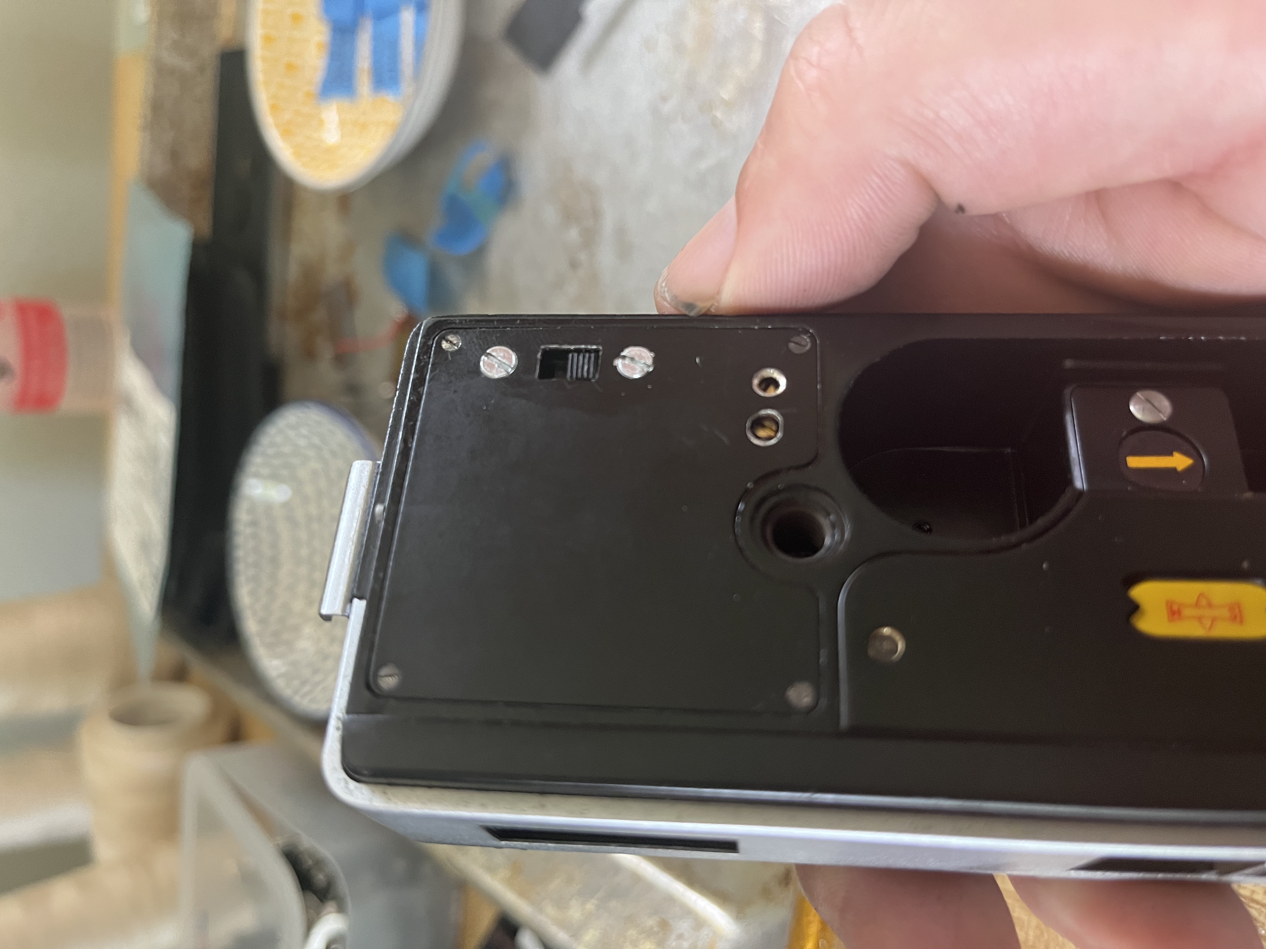 The bottom cover reinstalled showing the new meter level toggle switch and two new holes allowing access to the two calibration potentiometers. To calibrate the meter, I took the camera outside and took a reading with a reliable light meter, then adjusted the calibration screw till the meter needle was in the right place to pick the same aperture (assuming ASA 200 film and a 1/200 shutter speed).
Monocrystalline silicon solar cells do not have the same spectral response as selenium cells (selenium is less sensitive to longer wavelengths), and supposedly the linearity (amount of light -> power generated) is different, but the silicon cell seems reasonably accurate compared to my light meter over the 6ish EV range (the manual says 10.5 -> 16.5) that this camera is designed to meter. I checked a couple scenes in full sun, cloudy weather, brightly lit rooms. Apparently a lot of light meters use silicon cells with blue filters that cut out red light to match the spectral response of silicon more closely to film, and I considered sticking a blue gel in front of the solar cell, but I decided not to bother unless I notice that metering is really bad in certain settings (and modern film has plenty of lattitude so as long as I’m within a stop or two I should be able to get a decent image).
